View drilling data in Client (Drilling tab)
XECUTE has the ability to retrieve drill hole data from EPF and render drill holes in the 3D Scene. You can visualise this data in Client using the Drilling tab.
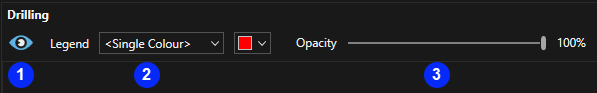
Tab menu
| Icon | Description | |
|---|---|---|
| 1 | Drill holes visibility | Toggle visibility of all drill hole data. |
| 2 | Legend |
The legend applied to the drill holes, options include:
|
| 3 | Opacity | The opacity of drill hole renders. |
Existing drill holes can be manipulated in such a way that you can:
- Change the colour scheme and colour rules applied.
- Filter out drill holes based on any available data field.
XECUTE will recognise two different types of drill holes - planned and actual.
Start by configuring XECUTE Config as described below and in the Data Feed In section. Once configured and enabled, the drilling data should appear in the Drilling tab in XECUTE Client. Select the Show Drilling check box in the upper left of the grid.
Setting up drill hole Data Feed In using XECUTE Config
Planned drill holes
Planned drill holes represent the outcome of a design process where drill holes are planned ahead of time. Once rendered, they should be considered as a guide.
In order to retrieve the planned drill holes, it is mandatory to create at least one Data Feed In of type Drill Hole - Plan in XECUTE Config.
Third party systems can publish and send drilling data to EPF with the corresponding fields.
| Field Name | Data Type | Mandatory | Description |
|---|---|---|---|
| Identifier | String | Mandatory | Unique identifier for the drill hole. |
| Sequence | Numeric | Optional | The drilling sequence for the hole. |
| Activity Area Name | String | Optional | The name of an associated activity area. |
| Status | String | Optional | The status of the drill hole. |
| Duration | Numeric | Optional | The planned duration of the drilling activity in hours. |
| Diameter# | Numeric | Optional | The planned diameter of the drill hole in mm. |
| Length | Numeric | Optional | The planned length of the drill hole in m. If the Geometry type is WKT 'MULTIPOINT Z' the length field is required. |
| Last Updated On | Date | Optional | Date last updated. |
Geometry data
In addition to these fields, the geometry of the hole must be defined and the geometry fields added to the dataset. The geometry can be defined as a pair of X, Y and Z values representing the top and bottom of the hole, or it can be specified in Well Known Text (WKT).
# - The default drill hole diameter. If no value is supplied a default value is used which results in thin drill holes. A suggested drill hole diameter is 2000 mm.
The Config drop-down list in the Drill Hole - Plan mapping area allows you to specify which of the geometry types you want to use.
Geometry specification method:
- X, Y, Z points.
- Well Known Text (WKT).
If X, Y, Z points is selected, the mapping area has the following fields added to the list:
| Field Name | Data Type | Mandatory | Description |
|---|---|---|---|
| Top of Hole X | Numeric | Mandatory | X coordinate for the top of the drill hole. |
| Top of Hole Y | Numeric | Mandatory | Y coordinate for the top of the drill hole. |
| Top of Hole Z | Numeric | Mandatory | Z coordinate for the top of the drill hole. |
| Bottom of Hole X | Numeric | Mandatory | X coordinate for the bottom of the drill hole. |
| Bottom of Hole Y | Numeric | Mandatory | Y coordinate for the bottom of the drill hole. |
| Bottom of Hole Z | Numeric | Mandatory | Z coordinate for the bottom of the drill hole. |
If Well Known Text (WKT) is selected, the mapping area has the following fields added to the list:
| Field Name | Data Type | Mandatory | Description |
|---|---|---|---|
| Geometry | String | Mandatory |
'MULTIPOINT Z' representing the point at the top of the drill hole. The length of the drill hole is then read from the Data Feed In Length field. 'LINESTRING Z' representing the drill hole top and bottom points. |
Actual drill holes
Actual drill holes represent the current drill holes on a site.
In order to retrieve the actual drill holes, it is mandatory to create at least one Data Feed In of type Drill Hole - Actual in XECUTE.Config.
For Actual data to display in the scene there must also be a Planned Drill Hole Data Feed In with a matching Identifier value.
Third party systems can publish data to EPF with the corresponding fields:
| Field Name | Data Type | Mandatory | Description |
|---|---|---|---|
| Identifier | String | Mandatory | Unique identifier for the drill hole. |
| Status | String | Mandatory | The status of the drill hole (to be used in the drilling legend). |
| Activity Name Area | String | Optional | The name of an associated activity area. |
| Last Updated On | Datetime | Optional | The date and time the last update was sent. |
Geometry data is required as per Geometry Date for planned drill holes.
For planned drill holes and actual drill holes that share the same Identifier, they will be merged into an actual drill hole with all the available information that might be part of the planned one. In other words, if there are two drill holes, one planned and one actual, and the actual is missing geometry information (diameter, length, geometry, WKT or Points) the renderer will try to use the planned drill hole to obtain those values.
Legend configuration
To apply a custom drilling legend to the holes first create a legend in XECUTE Config where the Name field contains expected status values. Select the custom legend at the Legend drop-down list and select the status field at the Legend Status drop-down list. The status value in the drilling Data Feed In will be mapped to the Name value in the legend.
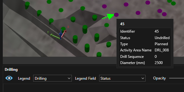
The image below shows drill data using a legend where the Name field values match the Status values from the Drill Hole - Plan Data Feed In. This mapping works here because both Name and Status are text data types.
Drilling Legend in XECUTE Config
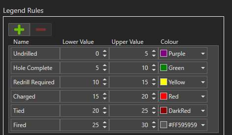
The legend Lower and Upper values are not used in this scenario because the Status field lookup matches the Name field.
If the selected Legend Field was a numeric value then the lookup would be performed against the lower and upper values of the legend.
Selection control
Double-click a drill grid row to zoom to the drill hole in the 3D Scene.
Select a drill hole in the 3D Scene to highlight it in the grids.